Options & Accessories
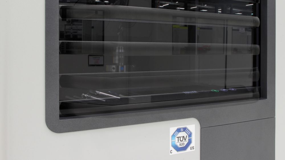
Automatic sliding door
Before starting the measuring process, the sliding door of the measuring machine can be conveniently and easily closed pneumatically via the software and opened again once the measuring process is completed.
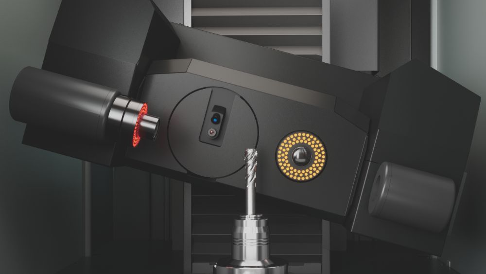
»orthoScan«
The swiveling multi-sensor optics carrier »orthoScan« always finds the perfect viewing angle on the tool. This means that the cutting edge geometries of tools with a pitch, such as taps or hob cutters, can be measured without distortion.
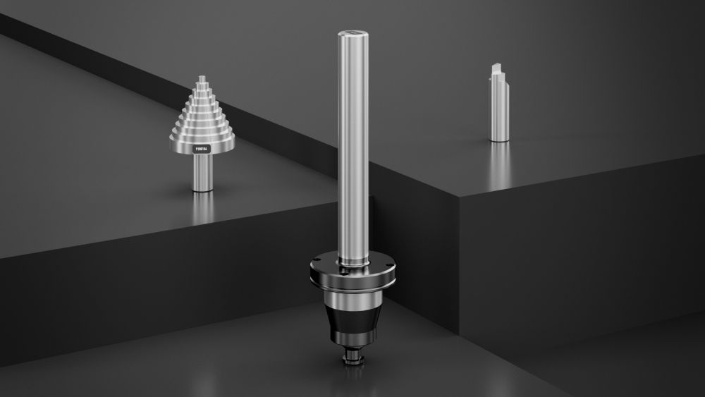
Tailstock counter point
With a clamping range of 300 mm for holding tools between points and for measuring exclusively using the snap gauge principle. The tailstock is removable and equipped with high-precision Hirth serration as an interchangeable interface.
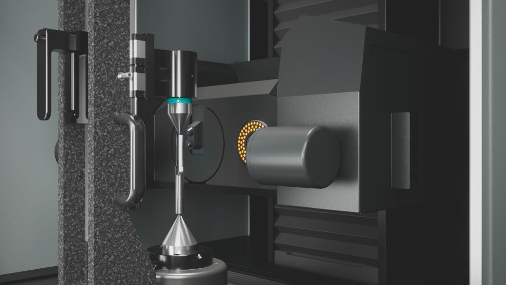
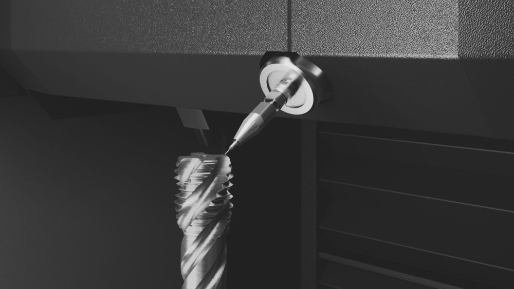
Scanning measuring probe
For electronic tactile measurement of, for example, the thread relief on taps. Available with probe inserts from D 0.01" to D 0.08" (D 0.3 mm to D 2 mm).
Measuring and inspection tools
For periodic on-site inspection of the measuring machine and to verify the accuracy of transmitted and incident light measurements, ZOLLER offers appropriate measuring and inspection tools for your measuring machine, such as test mandrels, diameter and angle test gauges.
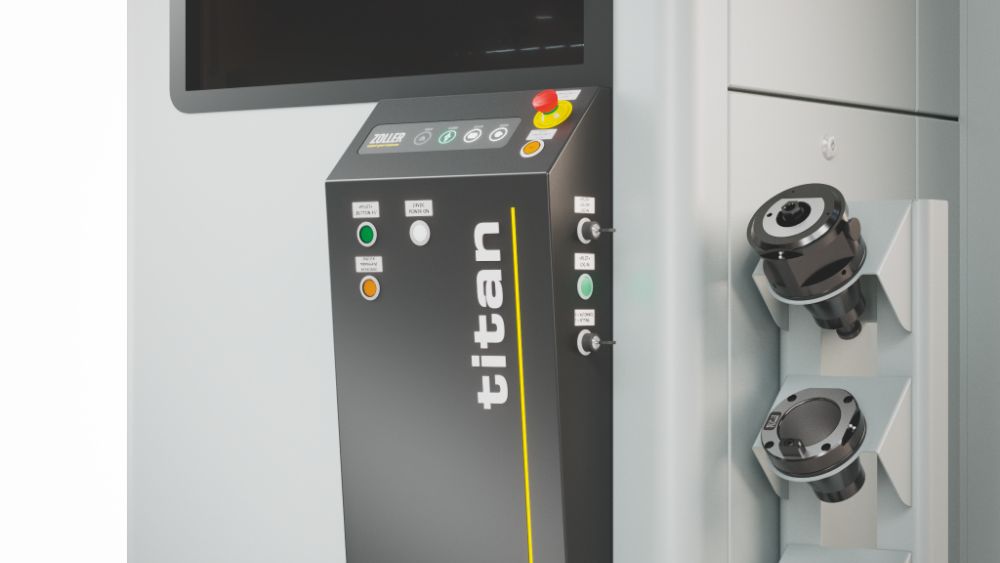
Safety package
Important operating elements are located on the front of the measuring machine. This means you always have unrestricted access to the emergency stop switch, the reset button, the membrane keypad and the button for starting measurement processes.
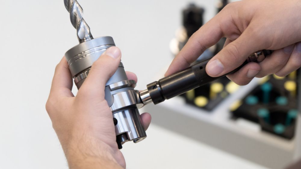
Manual RFID read/write station »mslz«
For manual writing/reading of the code carrier on the tool holder via a handheld reader.
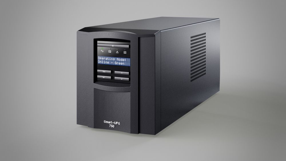
UPS system
The UPS system for uninterruptible power supply ensures that your computer is shut down properly in the case of a power failure to prevent data loss. Mains voltages of 230 V~ (Europe) and 120 V~ (USA) are available.
Sensors configuration
Optics transmitted light
Transmitted light camera HR70, BF approx. 0.15" x 0.14" (4.0 x 3.6 mm2)
Base model
Transmitted light camera 5 Mpx, BF approx. 0.21" x 0.19" (5.5 x 5.0 mm2)
optional
Transmitted light camera WF, BF approx. 0.61" x 0.55" (15.5 x 14.1 mm2)
optional
Optics incident light
Incident light camera HR70 Standard, BF approx. 0.04" x 0.03" (1.1 x 1.0 mm2)
Base model
Incident light camera HR70 Micro, BF approx. 0.01" x 0.01" (0.4 x 0.4 mm2)
optional
»zep« sensor (Cutting edge preparation)
optional
»zep-R« sensor (Cutting edge preparation/roughness)
optional
»Z3dCam« sensor (Digitization)
optional
Tactile
Scanning measuring probe
optional
Measuring machine configuration
Spindle
High-precision spindle »tcs«
Base model
High-precision spindle »ahd«
optional
Hollow encoder
Base model
Linear drive
Positive locking ball screw
Base model
X-, Y-axis in cross table design
Base model
Optics drive
Swivel axis incident light
Base model
Swivel axis incident light & transmitted light
optional
Vibration damping
Integrated, active with level control
Base model
Leveling element on machine feet
Base model
Material
Hard stone
Base model